
Transform Your Business with the #1 Software for Electronic Systems Contractors
Join thousands of AV, security, and technology professionals who use D-Tools to power their business operations, drive sales and maximize profitability.
Trusted By


D-Tools: The Heartbeat of a Thriving Business
D-Tools provides seamless, end-to-end solutions to manage every aspect of your integration workflow. From client engagement and project planning to installation and service, D-Tools connects proposals, resource management, and customer success into one streamlined platform.
Empowering efficiency and innovation, D-Tools frees your team to focus on delivering exceptional results. It’s more than software—it’s the catalyst driving growth, transformation, and success in your business.

Our Supplier Partners
.png)

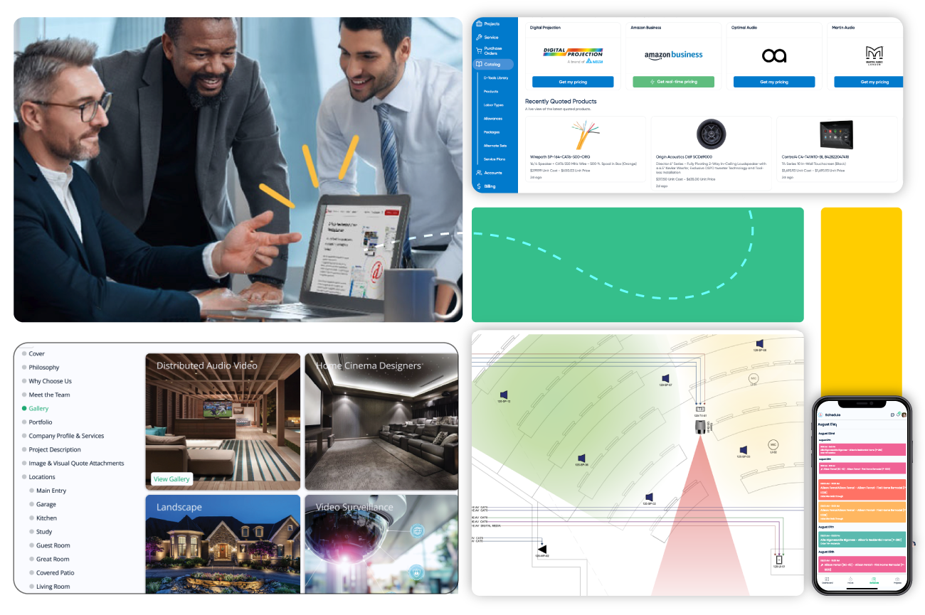
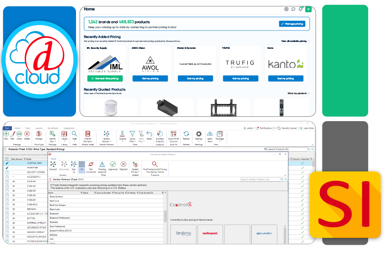
Power Your Workflow with the Industry's Largest Product Database
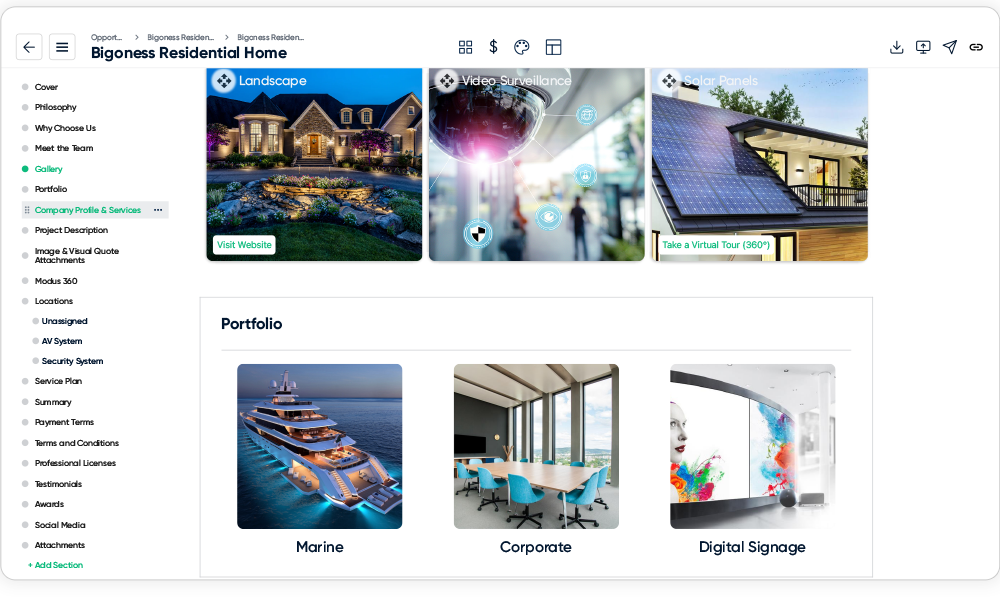
Optimize your proposals and system designs with D-Tools’ integrated product library—featuring 1.6 million products from over 1,200 brands, complete with integrator-level pricing. Simplify catalog management to reduce data entry time and help ensure accurate pricing on every project. More than just a repository, this extensive database serves as the foundation for quoting, design, and installation workflows, driving precision and efficiency throughout your business.
Optimize Critical Business Processes, from Beginning to End
.png?width=1500&height=971&name=sysdesign%20(1).png)
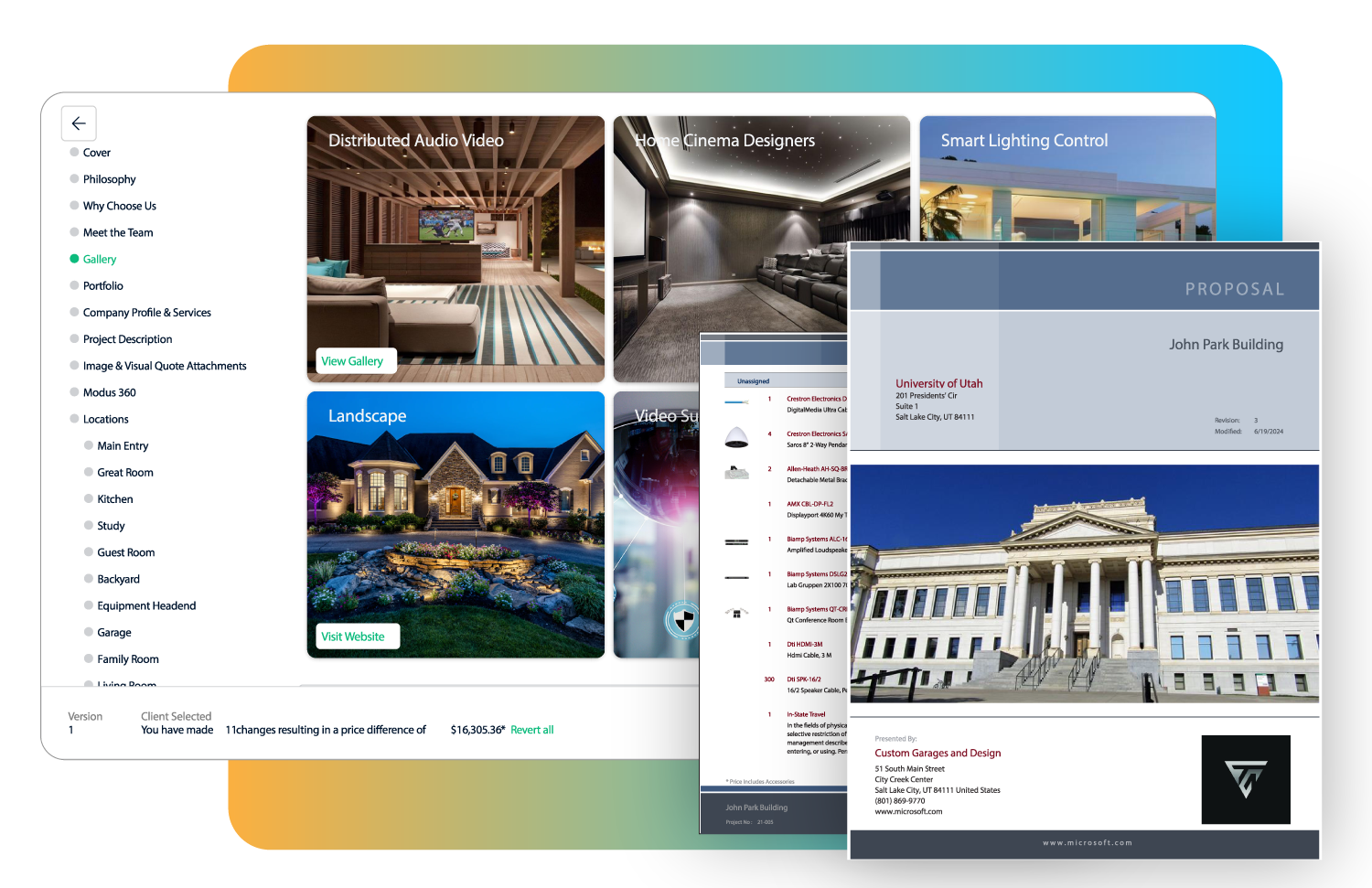
Sales
Enhance your professional image and simplify the sales process by effortlessly crafting polished and personalized proposals. Generate precise quotes featuring integrator-specific pricing, elevating your efficiency and delivering a seamless experience to your clients. Leverage precise estimating capabilities to guarantee accurate project assessments from start to finish.
Design
Maximize productivity, ensure accuracy. Detailed engineering drawings and in-app markup tools enable precise system design and visual quoting. Access up-to-date product information with detailed specifications, including dimensions, and inputs/outputs through our Integrated Product Library for highly accurate and detailed documentation.
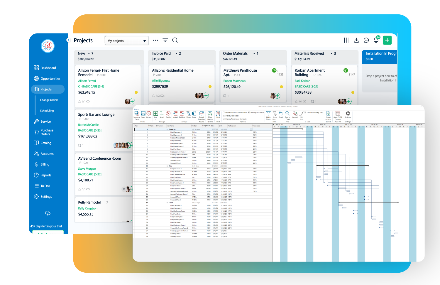
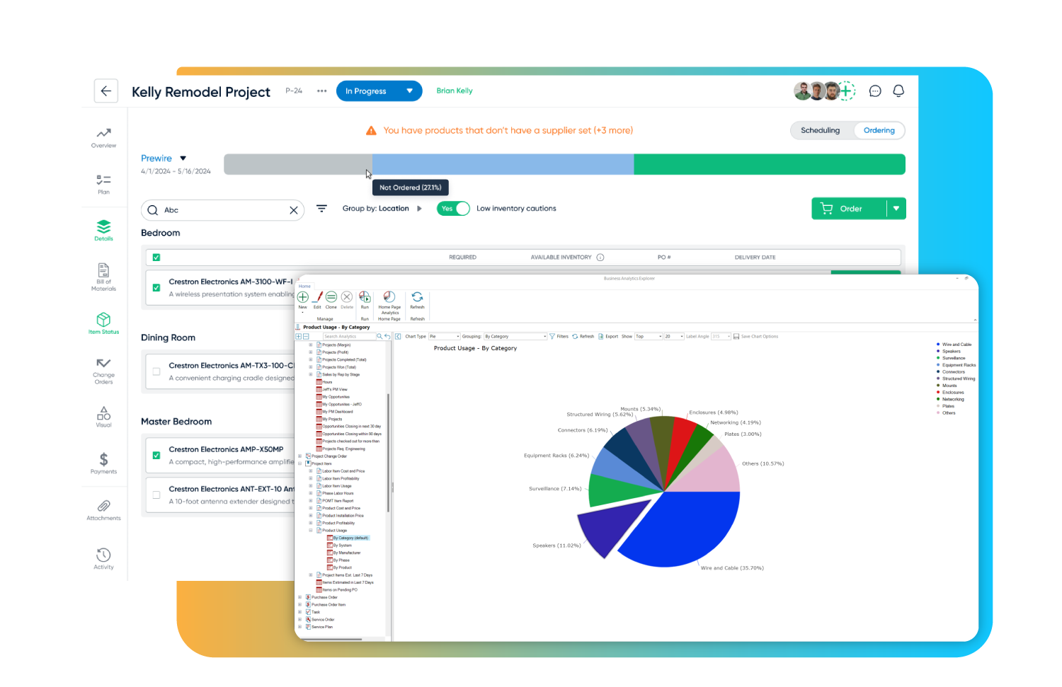
Project Management
Deliver your projects on time and on budget. Manage project workflows, from initial design through installation, with a detailed change order and management process. Gantt charts, task tracking and scheduling tools streamline workflows and effectively manage installations, service orders, and job costing. Schedule and dispatch field technicians to ensure installation tasks are completed efficiently.
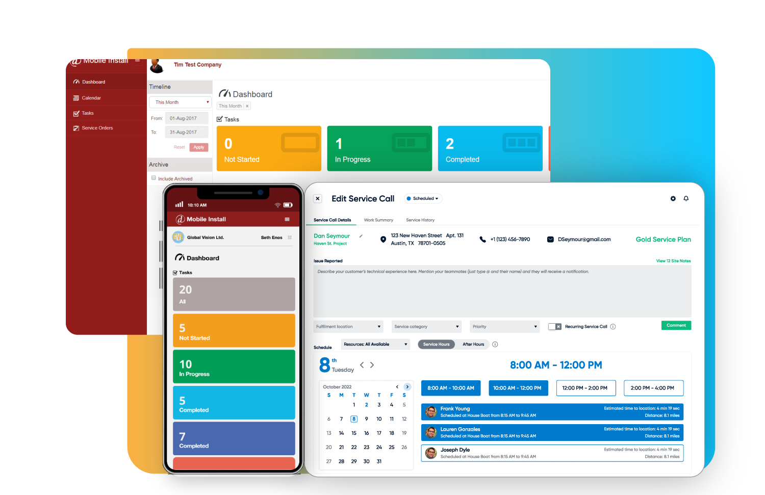
Service Management
Enhance client engagement by creating, presenting, and selling service plans with ease. Boost customer satisfaction and drive recurring revenue by seamlessly managing service requests, assigning resources, and scheduling service orders. Handle services tied to existing projects or service plans, or efficiently manage one-off service requests, ensuring smooth operations and long-term client relationships.
Back Office
Reduce costs, improve operational efficiency, and increase profits. Optimize payment processing, procurement and inventory management, and leverage 3rd party accounting integrations for maximum efficiency. Leverage visual reports and analytics to make data-driven decisions and optimize business performance.
Which Software Is Right for You?
 D-Tools Cloud
Easy-to-implement SaaS platform
- Sales pipeline tracking & management
- Intelligent Visual Quoting
- Multimedia Proposals w/e-signatures
- Embedded Payment Solution: D-Tools Payments
- Efficient project and service management capabilities
- Procurement & Inventory Management

.svg) System Integrator
System Integrator


Subscription Plans
Flexible Pricing Plans Tailored to Fit Your Business
D-Tools offers subscription plans designed to meet the unique needs of your business. Starting at just $99 per month, our flexible plans provide the tools you need to streamline operations and grow, all while staying within your budget.
D-TOOLS CLOUD PRICING
D-Tools Cloud subscription plans start at $99 per month - save 10% off the monthly rate when you pay annually.

SI PRICING
D-Tools SI starts at $150/user per month plus Professional Services implementation and optional hosting fees.
The D-Tools Difference
